Network diagrams are representations of network features or network objects that participate in a utility network or trace network. They exist with the network dataset as stored or temporary diagrams. For example, standard diagrams are always created on user demands as temporary diagrams. They are flagged as “to discard” in the geodatabase unless their creator decides to store them. On the other hand, the subnetwork system diagrams are never temporary; they are automatically created and maintained during subnetwork updates and always exist as stored diagrams in the geodatabase.
The following describes which diagrams to consider storing, the consequences of systematically storing network diagrams, and some recommended practices.
Good diagram candidates for storing
In general, consider storing diagrams with the following characteristics:
- They have a clearly organized layout.
- You may want to share them with other users—for example, for consulting or managing maintenance operations.
- They are built with Trace, Spatial Query or containment rules that enable relevant diagram updates.
- They represent a logical portion of the network.
- They show a stable set of junctions and edges over time.
As an example, an electric circuit subnetwork is a logical portion of a network. However, since it can cover a more reduced area after a switching job to balance the load over another circuit, it is not stable over time. With such an example, each circuit diagram is not separately a good candidate for storing. However, some sets of connected circuits that are used for load balance operations can be considered stable logical portions of the network and stored as diagrams for maintenance operations.
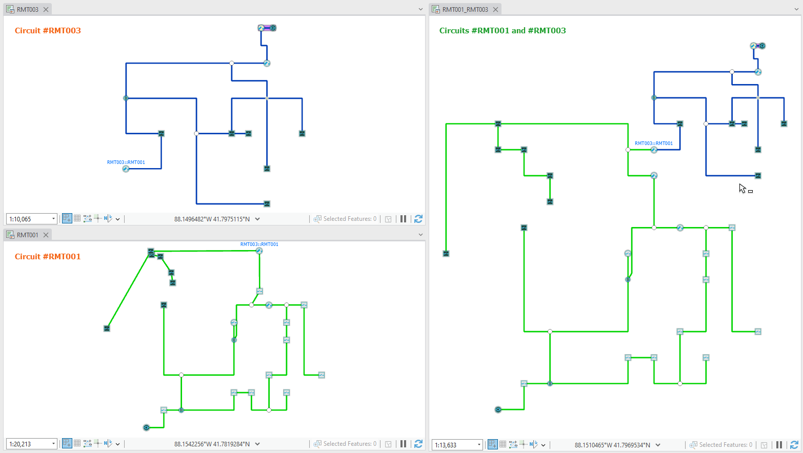
For example, see the sample graphics below:

On the left side in this first graphic above, you can see two simplified diagrams representing a circuit each, RMT001 and RMT003. On the right side, another diagram regrouping these two same circuits. They are connected to each other. These three diagrams show the two circuit states before a switching job to balance the load on circuit RMT001 over RMT003.
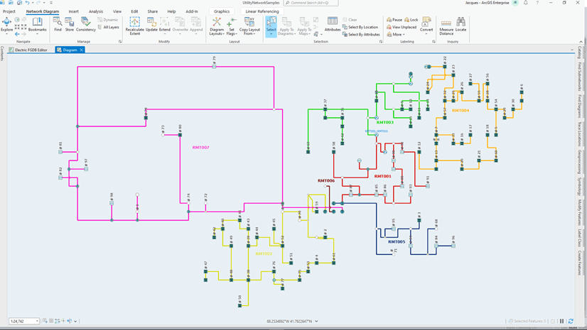
The second graphic above shows the same three diagrams once updated after the switching load operation. Due to the load balance, the RMT003 circuit now covers a more reduced area while the RMT001 circuit covers a larger area. This changes the content of the two single circuit diagrams on the left side. The diagram features representing the network elements that are no longer part of the RMT003 circuit are now part of the RMT001 circuit and display at their geographic positions in this single circuit diagram. On the other hand, the diagram representing the two circuits on the right side did not change its layout.
Through this example, you can see that instead of storing two diagrams, with each representing a single unstable circuit over time, you can store the one that regroups the two circuits where the content and layout stay stable.
Bad impacts of systematic diagram storage
Storing a diagram can have a real interest but should not be systematic. Storing diagrams impacts the geodatabase size and can slow down some operations.
Database size increasing
Stored network diagrams can increase the geodatabase size, in particular when the network exists in a branch versioned dataset. In this case, each time you edit a feature or object, a new row is systematically added to the feature class or table to record this change. This is the same for every diagram feature you edit in a stored diagram. Also, imagine a stored diagram covering a large part of the network. Even if this diagram shows a simplified portion of the network focusing on the only critical devices, both visible and aggregated network elements are stored in the geodatabase. When you apply a layout to the diagram, there is no change on its aggregated elements, but there are changes for every row corresponding to a network element you see in the diagram.
Also some operations such as Update Diagram, Overwrite Diagram or Delete Diagram can impact the branch versioned dataset size. For example, the subsequent deletion of any diagram that has been stored causes a new row to be created for each deleted diagram feature, whether this feature is aggregated or visible in the deleted diagram.
Slowdown of some operations
When setting the subnetwork definition for a tier, the administrator can specify one or many system diagram templates. In this case, each tier subnetwork is created in the geodatabase with subnetwork system diagrams for every specified system diagram template. Since subnetwork system diagrams are stored diagrams and systematically maintained during subnetwork updates, the Update Subnetwork operation is slower when system diagram templates exist for subnetworks.
Recommended diagram storage practices
Network administrators can control diagram storage and limit geodatabase size increasing. Users can also apply recommended practices during their workflow.
Tips for utility or trace network administrators
As the network administrator, you can act on the geodatabase size control at two different moments—during the diagram template configuration initial phase and during the production maintenance phase.
Limit diagram storage when configuring diagram templates
As the network administrator, when you set subnetwork definitions for network tiers, you must think about whether you want to automatically create and maintain system diagrams during subnetwork updates for every subnetwork. You can set this using the Subnetwork Diagram Templates parameter when running the Set Subnetwork Definition tool. Before filling this parameter, you must consider alternative workflows that could better fit user expectations. For example, instead, you can provide users with diagram templates based on a subnetwork trace rule that they can use to manually create standard subnetwork diagrams for only the subnetworks they are interested in. Moreover, with this diagram template available, they are not limited to diagrams that each represents a single subnetwork. They could use this same diagram template to create diagrams representing multiple subnetworks, such as the sample diagram representing two connected circuits on the right side in the graphics above. Another example is diagrams representing the distribution subnetworks in a given quarter or those covering a water pressure zone.
You can also allow users to store diagrams or prevent diagram storage at the template level. Check or uncheck the Enable diagram storage parameter when you run the Alter Diagram Template tool. When this parameter is not check for a template, users cannot store diagrams based on this template.
Control geodatabase size increases
Even without storing any diagrams, the geodatabase size increases each time users create temporary diagrams. Any temporary diagram in the geodatabase is discarded but still exists in the diagram tables. Compared to stored diagram tables, temporary diagram tables that are not versioned do not grandly increase the geodatabase size but must be regularly controlled. As the network administrator, consider using the Purge Temporary Diagrams tool to schedule a scripting task to regularly purge the temporary diagram tables.
Advice for users
As a network diagram user, you do not need to systematically store every diagram you generate even when nothing prevents you from storing it. For example, do not store network diagrams that you create for one-time use to see how network stuffs are connected to each other. In general, any network diagram that you can easily create should never be stored. Remember that when a network exists in a branch version dataset, even if it changes daily, you can connect to a historical moment at any time and create a temporary diagram that will reflect your network state at that specific past moment.
In general, only store network diagrams that you carefully laid out; for example, those for which you did manual edits that you do not want to lose.
You can also store a few network diagrams that you want to share with other users, for example, users with a restricted access who can only view network diagrams.
This is also recommended if the set of diagram features in the diagram you want to store is stable over time to avoid having to refine a diagram layout following any updates.
Finally when working on branch versions, consider limiting network diagram edits in the branch for any diagrams that already exist in Default. For example, you do not need to update a diagram after network changes you did in your branch since it must be updated anyway after you post your version. Also after reconciling and posting your version, delete the branch if you finished with it.
Summary
Whether you are a user or the utility or trace network administrator, you must weigh the pros and cons of storing network diagrams. Do not clutter the geodatabase unnecessarily with network diagrams that have no use or that users can re-create in one click at any time. Store network diagrams that are clear, cover logical portions of the network, and are useful to share with other users.

Article Discussion: